555 And Tsop1738 Ir Remote Control Circuits
IR Remote Controller Fan Regulator using AT89C2051 is a simple circuit which can control the speed of fan (you can also use this circuit to control the intensity of light; light dimmer). Previously we have posted very interesting project on fan regulator called Light Controlled Digital Fan Regulator that uses torch light to control the speed of fan.
In every remote control there are two parts1) Transmitter2) ReceiverTransmitter:-The schematic of transmitter is as shown in Circuit Diagram tab1. It is basically astable multivibrator made up of. It generates square wave of 38KHz. Whenever you press switch S1 the chip (U1) will start generating continuous square wave of 38KHz at its output pin No. The output is fed to through transistor BC546, which is used to provide sufficient current to LEDs. So the circuit will generate IR light beam of 38 KHz. The range of this transmitter is around 3 meters.
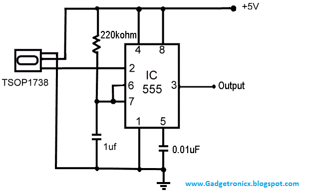
If you don't want to build this circuit then also it is ok. You can use any other standard remote control used for TV or music system as a transmitter. The range of that remote control is around 10 meters.Receiver:-The schematic of receiver is as shown in circuit diagram tab2.The main components of the circuits are IR sensor , IC MCT2E (opto-coupler) IC 555, and IC 74LS107 (JK flip flop).The IR light beam of 38 KHz is sensed by IR sensor TSOP 1738. The sensor has a property that it gives continuously high output at pin no. And whenever IR light is detected it gives low output pulse.The output of sensor is connected to input of opto-coupler IC MCT2E. Because of the low pulse input at pin no. 2 this chip will generate same low pulse at its output pin no.
5.This output pin is connected to triggering input (pin no. 2) of IC 555. IC 555 is connected in mono stable mode. So it will generate high o/p pulse of 1 Sec. (time determine by RC components R5 & C1) when ever it's triggering pin no. 2 receives low pulse.The output of IC 555 is given as a clock input to JK flip flop IC 74LS107. Both J & K inputs are connected to Vcc.
So it will work as T flip-flop. Output of T flip-flop toggles every time. Means if it's high then on receiving clock pulse it will be low and vice versa.This output is amplified by two transistors (2N2222A) to drive relay.
The relay connections (C & N/O) are used to switch any 230V device (e.g. Bulb used here).Operation: -. When you press switch S1 of transmitter it will generate IR light beam of 38 KHz. This beam will be sensed by IR sensor and it will produce low pulse. This low pulse will trigger IC MCT2E and it will also generate low pulse at its output.
555 And Tsop1738 Ir Remote Control Circuits Work
This low pulse will trigger mono stable multivibrator and it will generate clock pulse of 1 sec. For JK flip flop. On receiving of clock pulse output of flip flop will toggle means if it was low then it will be high and vice versa. The o/p of flip flop will change relay connections from N/C to N/O. So the bulb (or any device) will be switched ON.
Ir Rf Remote Control


again when you press switch S1 from transmitter same thing will happen but now the o/p of flip flop will toggles from high to low so relay will be switched from N/O to N/C and the bulb will be switched OFF. Thus every alternate time when you press switch S1 the bulb will be switched ON or OFF.Circuit Diagram.
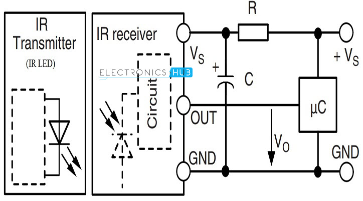
Sensor Pinouts How connect Supply Voltage to TSOP1738The following image shows how the TSOP1738 IC needs to be wired and connected across a given supply voltage and how its output may be terminated to the relay driver circuit for the intended toggling of the relay according to the sensor's response to the IR signal.The shown wire connections are for indicative purpose only, these could be in practice connected through PCB tracks. That’s great jayanth,to latch you can connect a diode between the base of the middle BC547 and the collector of the relay driver BC547. Cathode will go to the collector.Also connect a 1K resistor across the base and ground of the middle BC547 transistor.But remember, with this arrangement the circuit will be latched initially when power is switched ON. You must have switch in series with this diode so that you can keep the diode disconnected initially and switch it ON only once the IR beams is correctly focused on the TSOP.
